
Detector Concept of pn-CCDs
pn-CCDs are backside illuminated, 3-phase CCDs on a fully depleted silicon substrate. Their functioning is based on the principal of sideward depletion. A schematic drawing is shown in the picture below. In contrast to commonly used MOS-CCDs, the transfer registers of a pn-CCD are formed by pn-junctions. This allows for high radiation hardness, fast transfer modes and high full-well capacitances. The ultrathin and unstructured radiation entrance window enables a high quantum efficiency from the near IR and optical to the X-ray regime.
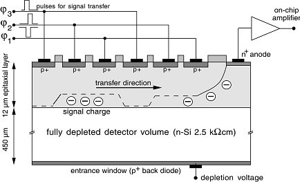
Schematic cut through a pn-CCD.
To enable low noise and high frame rates, each channel of the CCD is has its own on-chip amplifier. The amplified signals of one CCD line are fed in parallel into an amplification chip (CAMEX), where all signals are further filtered and shaped in parallel. The following picture shows a zoom of the readout region of the CCD, comprising two readout anodes, connected to the on-chip amplifiers.
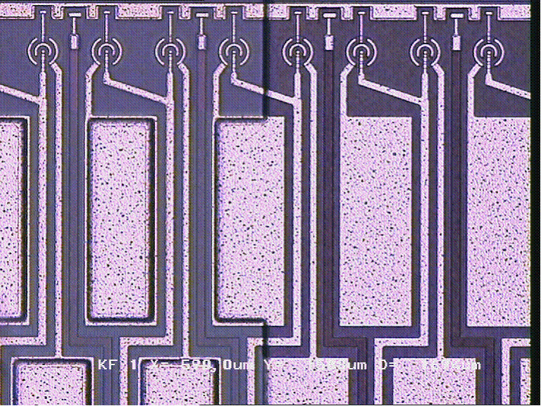
Readout region of a pn-CCD, showing two readout anodes connected to on-chip amplifiers.
[up]
pn-CCDs for X-ray Astronomy
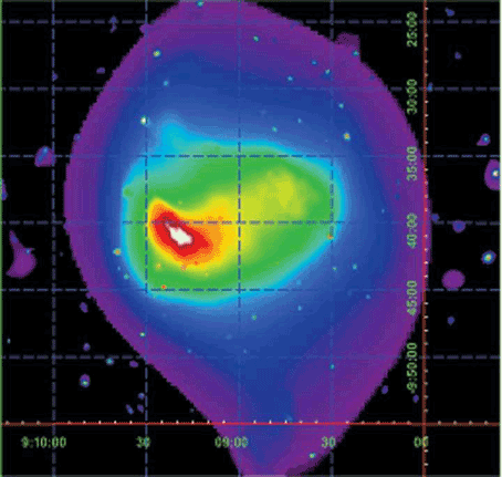
The Max-Planck-Institute for Extraterrestical Physics has developed together with the Semiconductor Laboratory of the Max-Planck-Institutes and the staff of PNSensor the largest defect free X-ray CCD ever built with a sensitive area of 6 x 6 cm² for the XMM-Newton satellite mission which was launched successfully in the year 1999. The CCD in the central focal area follows the pn-CCD concept.
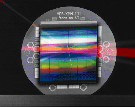
The largest X-ray CCD ever build, with a sensitive area of 60 × 60 mm².
The CCD was developed for the XMM-Newton satellite mission.
[up]
Detector Modules
For operation, pn-CCDs are packed onto a ceramic carrier board, together with the CAMEX readout chip and RC-filters to ensure clean and stable supply voltages.
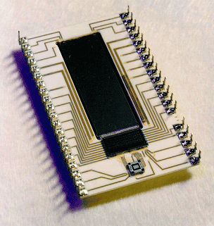
Picture of a 64 × 200 pixel pn-CCD, mounted on a ceramic carrier together with the CAMEX readout chip.
The CCD has a sensitive area of 3 cm²
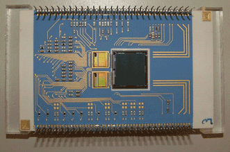
256 × 256 pixel CCD with 50 µm pixel size. The 256 channels of the CCD are
read out by two CAMEX chips, having 128 channels each.
[up]
System Set-Up
In set-up of the pn-CCD system the ceramic boards of the CCD module are fixed between cooling masks in order to enable a cooling of the CCD to its operating temperature. The masks are connected by flexible copper wires to a cooling system and the vacuum chamber. For the cooling system several types have between tested and are operated in our laboratory:
- a closed cycle He-system
- stirling cooler
- cryo Tiger
- liquid nitrogen dewar.
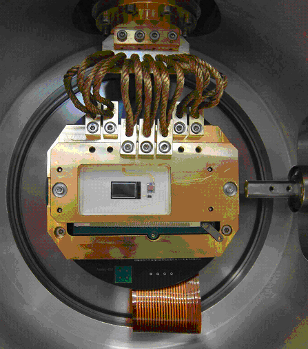
A ceramic board with CCD mounted in a laboratory testing facility.
The system is operated and read out by the compact pn-CCD controller containing all power supplies, the sequencer and ADC allowing for high-speed high-precision data acquisition.
[up]

